Documentation
Dataset Description
The provided data package covers various environments including indoor, outdoor filed, outdoor close to structures, and semi-enclosed areas. Several maneuvers have been done to make sure that different angles and distances between the UAV and sensor anchors are covered. The dataset is collected from 2018 to 2020. This resulted in over 7 hours of flight with collected UWB and IMU data along with total station as ground truth.
| Name | Environment | Location | Area | Number of datasets |
|---|---|---|---|---|
| Indoor | Indoor | Oshawa, Ontario, Canada | 26m(w)×33m(l)×10m(h) | 5 |
| Field | Outdoor- field | Soccer field, Uxbridge, Ontario, Canada | 12m(w)×13m(l) | 5 |
| Building | Outdoor- Close to structures | Building, Newmarket, Ontario, Canada | 7m(w)×7m(l) | 3 |
| Bridge | Semi-enclosed area- Under a concrete-metal bridge | Niagara, Ontario, Canada | 10m(w)×23m(l)×6m(h) | 4 |
| Tunnel | Semi-enclosed area- Under a concrete tunnel | Oshawa, Ontario, Canada | 8m(w)×30m(l)×3m(h) | 4 |
Datasets provided in this research
 |
 |
 |
 |
 |
Different environments used for collecting datasets
 |
 |
 |
 |
 |
 |
 |
 |
 |
 |
 |
 |
Sample images from different flights in the datasets, showing variation in trajectories
Sensor Suite

Sensors and UAV Configuration

UAV Platform
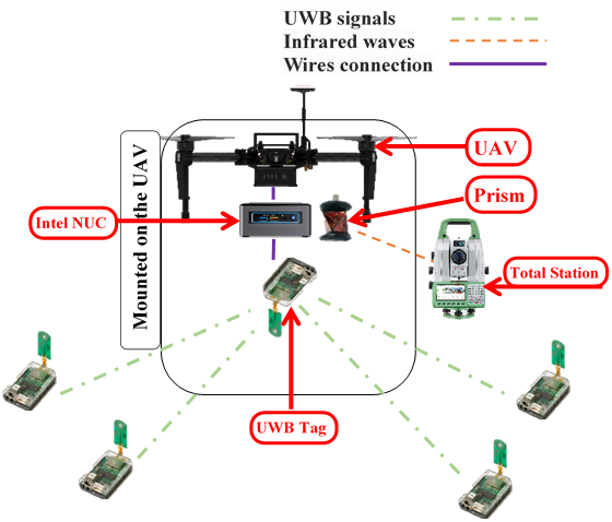
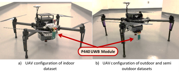
The UAV that is used in these experiments is DJI Matrice 100 that is a professional UAV that allows mounting up to 2.4 kg payload on it which is enough for our payload consist of UWB tag, Intel NUC computer and battery that is 112, 728 and 542 grams, respectively. The UAV (DJI Matrice 100) is equipped with the following items:
- UWB TIME DOMAINTM P440 UWB tag
- Computer Intel NUC computer
- Prism GRZ101, 360° mini prism
- External battery
UWB Anchor System
TIME DOMAIN used to make Ultra-Wideband (UWB) radio transceiver calling P400. In this experiment, we used total 5 PulsON 440 (P440) modules which is one of the P400-family. UWB anchors are four UWB tags mounted on tripods at different heights in a square shape arrangement on the ground. By using Time-of-Flight (TOF) method it can provide distance measurement between two or more sensors by 2 cm accuracy and up to 125 Hz rate. It can work in temperatures above 40oC and lower than 85oC in high shock and high vibration environments.
Total Station
In order to have ascertainable and reliable data to validate position methods, we used the robotic total station which is a discontinued prism tracking total station. One GRZ101, 360o mini prism is mounted on the UAV and the total station actively tracks it using a modulated infrared light wave. Due to its small size, the GRZ101 provides the greatest pointing accuracy of 1.5 mm. For the indoor, bridge and tunnel datasets, Leica Nova MS60 MultiStation is used with the ability to measure range up to 1000m with 1” (0.00027o) angle accuracy. For the outdoor dataset Trimble VX Spatial Station with the ability to measure up to 5,500 m with 4 mm accuracy and 0.4 sec measurement time is used.
Communication System
Flight platform of DJI Matrice 100 can be customized through onboard SDK. The mounted NUC computer is connected to the Micro-USB port on the UAV. The SDK allows the computer to communicate with the flight controller and onboard sensors. Through this SDK, onboard IMU data is feeding online to the computer. Another mounted sensor on the UAV is UWB tag. It is connected through USB to the computer and a stream of data including ranges between the UWB antenna installed on the UAV and 4 antennas on the ground is being sent to the computer. Another sensor mounted on the UAV is a prism that measures the XYZ using the total station.
Data Format
The data are available in xlsx csv json formats. The data provided in each file is:
- IMU: angular velocity -x, -y, -z, linear acceleration -x, -y, -z, orientation quaternion -x, -y, -z, -w Height value
- UWB: Time(sec), Module ID, Range
Calibration is not applied to the data and the data is raw in the UWB anchors coordination system. In addition to sensor data, the optional correction coefficients for each dataset is provided. Also, a preview of each trajectory is available. Synchronized video of most of the datasets are available and is a big help to see the effect of environment and flight situation in data changing.
Range Calibration
The configuration of the sensors on the UAV is designed in a way to help the UWB range data and ground truth range to be close. Also, during the flight, the pilot tried to keep the UAV stable but due to circumstances of different environments the data do not totally match, and they can be calibrated using correcting coefficients (1). These coefficients are measured by minimizing the error between the rectified range and ground truth range.
$R_{cal} = aR_{UWB} + \overline{b}$
$S = \sum_{i=1}^{N}(aR_{UWB} + \overline{b} - R_{GT})^{2}$
Intrinsic calibration look-up-tables are provided on the downloads page.
Structure of dataset
| 2 | ||||||||||
|---|---|---|---|---|---|---|---|---|---|---|
| 43.29807 | -0.00065 | -0.00238 | -0.0028 | -0.1055 | 0.068603 | 9.726355 | -0.00528 | 0.002525 | 0.976708 | 0.214495 |
| -1 | 7.687293 | 7.717323 | -0.0557 | |||||||
| 3 | ||||||||||
| -0.00011 | ||||||||||
| -1 | 7.687292 | 7.717323 | -0.05571 | |||||||
| 2 | ||||||||||
| 43.3052 | -0.00029 | -0.00219 | -0.00198 | -0.10695 | 0.063897 | 9.717726 | -0.00528 | 0.002521 | 0.976709 | 0.214487 |
| -1 | 7.687292 | 7.717323 | -0.05571 | |||||||
| 0 | ||||||||||
| 43.30995 | 100 | 10.339 | 0.055 | |||||||
| -1 | 7.687291 | 7.717323 | -0.05571 | |||||||
| 2 | ||||||||||
| 43.31808 | 0.000541 | -0.00215 | -0.00322 | -0.11773 | 0.046278 | 9.714664 | -0.00529 | 0.002519 | 0.976711 | 0.214478 |
| -1 | 7.687291 | 7.717322 | -0.05571 | |||||||
| 3 | ||||||||||
| -0.00012 | ||||||||||
| -1 | 7.68729 | 7.717322 | -0.05571 | |||||||
| 2 | ||||||||||
| 43.32515 | 0.001286 | -0.00205 | -0.00376 | -0.12942 | 0.037447 | 9.717512 | -0.0053 | 0.00252 | 0.976713 | 0.214472 |
| -1 | 7.68729 | 7.717322 | -0.05571 | |||||||
| 0 | ||||||||||
| 43.331 | 101 | 8.021 | 0.056 | |||||||
| -1 | 7.687289 | 7.717322 | -0.05572 | |||||||
| 2 | ||||||||||
| 43.33872 | 0.001027 | -0.00188 | -0.00458 | -0.13301 | 0.039272 | 9.723468 | -0.00531 | 0.002525 | 0.976713 | 0.214469 |
| -1 | 7.687289 | 7.717322 | -0.05572 | |||||||
Structure of dataset sample
Raw Data:
- UWB data
- [row 1] 0
- [row 2] Time(sec), Module ID, Range, Self-range error
- IMU data
- [row 1] 2
- [row 2] Time(sec), angular velocity-x, angular velocity-y, angular velocity-z, linear acc-x, linear acc-y, linear acc-z, orientation quaternion-x, orientation quaternion-y, orientation quaternion-z, orientation quaternion-w
- Height
- [row 1] 3
- [row 2] Height value
